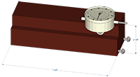
Construction:
- The jig is very easy to make and can be made from a chunk of scrap lumber.
- Create a rabbet along a length of lumber (length is not critical - mine was 7 3/4")
- Two pan head screws were inserted near the bottom of the jig leaving room for the heads to clear the surface it is placed onto.
- One of the screws was placed directly below and inline with the plunger of the dial indicator.
- The second screw should be sunk to the same depth as the first (check with calipers) and off to the opposite side of the jig.
- The purpose of the second screw is to keep the jig square to the surface being measured.
- When attachng the dial indicator, keep the plunger as close to parallel with the jig base as possible.

Usage:
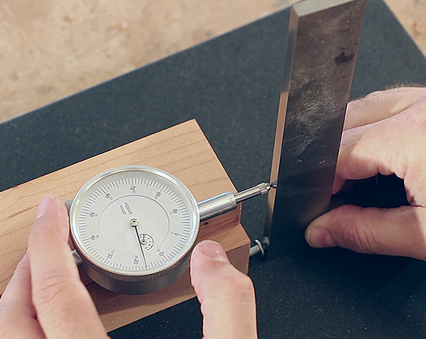
- When zeroing the dial indicator with a 90° square keep the square in line with the body of the jig (see first image above).
- The amount of error can be closely approximated by measuring the distance (D) on center between the plunger and the screw below the plunger. In my case the distance (D) is 2 1/4" therefore we can calculate, by assuming the plunger is parallel with the jig body, the angle error from 90° (this is a VERY close approximation of the angle error).
- To caluculate the amount of angle error for your jig, use the equation below, where "error" is the measured distance from your dial indicator.
- You can also use my online calculator (Tan Math) where 'Adjacent' is 'D' above and 'Opposite' is the distance measured by the dial indicator.
Questions?
|


